
Crane Fabrication & EOT Crane Structures in India
A crane girder failure does not just stop production. Depending on the type of crane and the load it is carrying, it can kill people. That is why crane girder fabrication demands more care — more thorough inspection, tighter dimensional tolerances, more rigorous documentation — than most structural steel work. At Suncorporation, crane fabrication and EOT crane structures are a core workshop specialisation, and crane girder work is one component of that package. We have been fabricating EOT crane runway beams, under-slung crane track systems, and complete crane bay structural steel for industrial clients across India for over 20 years.

This page covers crane fabrication and EOT crane structures — the supporting steel around industrial cranes, including columns, brackets, and runway steel. Crane girders remain part of that package; for dedicated girder specifications, spans and RFQs, review our crane girder structures product page. If you have crane layout drawings and wheel load data, send them to us and we will have a quote back within 48 hours.
What a crane girder actually is and why it matters
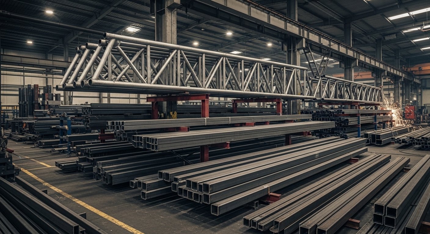
A crane girder — also called a gantry girder or runway beam — is the steel beam that runs along the top of the crane bay at high level, supporting the crane rail on which the end carriages of the overhead travelling crane run. The crane wheel loads transfer through the rail into the top flange of the girder, and from there through the girder to the crane columns and into the foundations. Every time the crane accelerates, brakes, or swings a load, the girder absorbs dynamic forces in addition to the static wheel load. Over the life of a factory — which might be 40 or 50 years — a heavily used crane girder goes through millions of load cycles. Fatigue is a real design consideration, not a theoretical one.
IS 807:2006 — the Indian standard for the design, erection, and testing of cranes and hoists — recognises the fatigue issue by classifying cranes by duty class and specifying different design requirements for different duty levels. There is no such thing as a generic crane girder that fits any application.
How crane fabrication is executed at Suncorporation
Crane girder fabrication starts with the crane layout drawing from the crane supplier and the structural design from the structural engineer. Problems arise when the fabricator starts work before these two documents are reconciled. At Suncorporation, we request both documents before preparing shop drawings. If there are discrepancies — wheel loads on the structural drawing that do not match the crane supplier’s updated data sheet, clearance requirements that conflict with the proposed girder depth — we raise them before fabrication begins, not during.
Web and flange plate preparation
The web and flange plates for crane girder fabrication are cut on our CNC plasma table, which gives us edge straightness and squareness that manual cutting cannot match. For heavy crane girders — runway beams for cranes above 30 MT capacity — the flange plates are typically 25 to 50mm thick and the web plates 16 to 20mm thick. We check flatness, dimensional accuracy, and mill test certificate traceability for every plate before it enters production.
Assembly, welding and camber setting
The web and flange plates are assembled in a dedicated jig and the longitudinal fillet welds are made using our SAW equipment for heavier sections. Stiffener plates are welded to the web at the positions of the crane columns, at mid-span for longer girders, and at the end of the girder. Stiffener-to-web and stiffener-to-flange fillet welds are inspected by MPI after completion. Every crane girder needs positive camber — IS 807:2006 specifies the minimum camber as L/1000, where L is the span between support points. Camber is set during fabrication and verified by survey before painting.
NDT and inspection
Crane girder fabrication at Suncorporation includes UT inspection of all full-penetration butt welds — flange splices, web splices, and any other full-penetration welds in the girder. MPI is applied to all fillet welds in the flange-to-web connections, the stiffener connections, and the top flange reinforcement plate welds. For girders carrying cranes above 20 MT capacity, we recommend third-party NDT in addition to our in-house inspection. All dimensional inspection records — overall girder length, depth, flange width, camber profile, bolt hole positions, rail seat flatness — are included in the project quality dossier.
Crane columns and bracket seats
The crane girder does not sit on the same column as the main building frame in most industrial shed designs. It sits on a separate crane column with a bracket welded to it at the level of the crane girder bottom flange. Crane column fabrication is part of the complete crane girder fabrication package at Suncorporation. We fabricate the crane columns — typically heavy UC sections or welded box columns for large cranes — with the welded bracket seats, base plates, and anchor bolt templates. All bracket-to-column connections are inspected by MPI.
Under-slung cranes and monorail track systems
Under-slung cranes and monorail hoists — where the hoist and crab run on the bottom flange of the track beam — are widely used in Indian industry for lighter loads up to 5 MT. Suncorporation fabricates under-slung crane track beams — straight sections, curved sections to specified radii, and all associated support steelwork including hangers, brackets, and end stops. We supply the complete under-slung system as a numbered kit with installation instructions.
Crane fabrication cost in India — 2026 rates
- Runway beams for cranes up to 10 MT, spans up to 12m: Rs 90,000 to Rs 1,05,000 per MT supply, excluding erection.
- Runway beams for cranes 10 to 30 MT, spans 12 to 20m: Rs 1,05,000 to Rs 1,25,000 per MT supply. UT on flange splice welds, MPI on longitudinal fillet welds.
- Runway beams for cranes 30 to 60 MT, spans 15 to 25m: Rs 1,20,000 to Rs 1,45,000 per MT supply. Heavy plate, full UT and MPI, third-party NDT recommended.
- Crane columns with brackets: Rs 85,000 to Rs 1,10,000 per MT depending on section size.
- Under-slung monorail systems up to 5 MT: Rs 80,000 to Rs 1,00,000 per MT for the track beams including curves and switches.
IS 807 and the standards that govern crane girder fabrication in India
IS 807:2006 governs crane girder fabrication and crane supporting structure design in India — duty class classification, fatigue load spectrum, minimum camber, deflection limit under crane wheel load, and tolerance requirements for rail alignment. IS 800:2007 governs the structural design of the crane supporting structure. IS 875 Part 2 specifies imposed loads including crane wheel loads. IS 1893 applies in seismic zones for the crane supporting structure design.
Enquiries for crane fabrication and EOT structures
To get a quotation for crane fabrication and EOT crane structures from Suncorporation, we need the crane layout drawing from your crane supplier, the structural engineer’s girder design or a specification of the crane capacity and span, and the site location. If the structural design is not yet complete, the crane capacity, span, and duty class are enough for a budget estimate. We respond to all crane girder fabrication enquiries within 24 hours.
Contact Suncorporation for crane girder fabrication. Also see: Heavy steel fabrication | Industrial shed fabrication | Structural steel Hyderabad