
Plate Girder Fabrication India
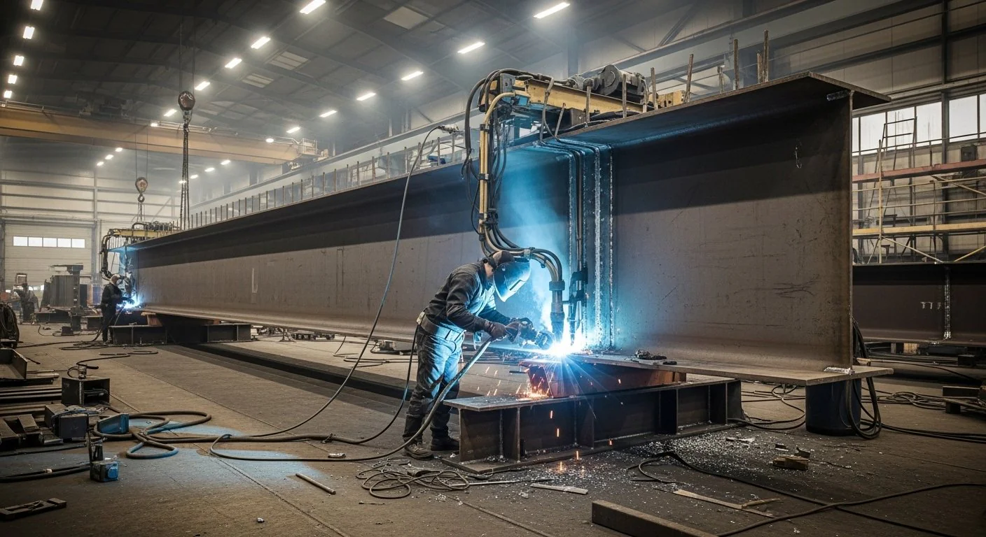
Plate girder fabrication is the shop assembly of welded I-girders and box sections from IS 2062 plate — web plates, flanges, stiffeners, and connection plates cut, fit, and welded to the structural engineer’s approved shop drawings. Sun Corporation fabricates plate girders at our Jeedimetla workshop for road-over-bridge approaches, industrial access spans, crane runway segments, and pipe bridge longitudinals, with WPS/PQR documentation and NDT per the project ITP.
Rolled beams stop being practical when the design needs a deeper web, a thicker flange, or a non-standard flange width. A plate girder lets the engineer size each element separately: web thickness for shear, flange area for bending, and stiffener layout for buckling control. That flexibility is why plate girders appear on long industrial spans, ROB approaches, and heavy crane runways where a catalogue UB section would be oversized in one place and inadequate in another.
We fabricate and erect to the approved design with full material and weld traceability. We do not provide independent statutory structural design — the engineer’s drawings and the project code govern geometry, camber, and connection details.
Types of plate girders
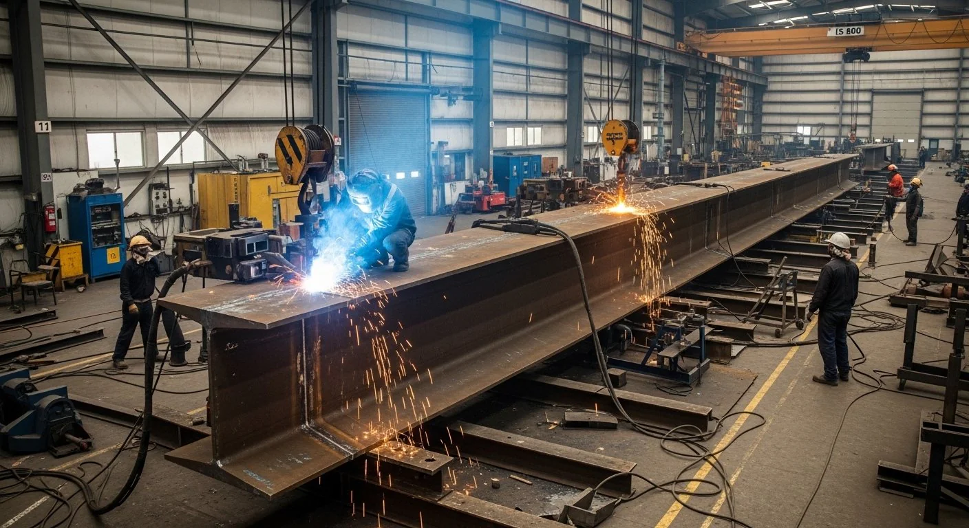
- Welded plate girders — the standard shop-fabricated I-section with web and flanges joined by continuous fillet or butt welds.
- Built-up plate girders — multi-plate flanges or reinforced webs where a single plate thickness is not enough for the design load.
- Straight plate girders — constant-depth girders for industrial spans, access bridges, and pipe bridge longitudinals.
- Variable-depth / haunched girders — depth increased at supports or mid-span as shown on the drawings, common on ROB approaches and long industrial spans.
- Heavy-duty plate girders — thick-plate assemblies for crane runway segments and other high concentrated-load applications, often coordinated with crane girder structures.
- Box sections — closed welded sections where the design requires high torsional stiffness.
Structural components
- Web plate — the vertical plate carrying shear between flanges.
- Top and bottom flanges — plate flanges sized for bending compression and tension.
- Bearing stiffeners — stiffeners at supports and load points to prevent web crippling.
- Intermediate stiffeners — transverse (and where required longitudinal) stiffeners controlling web buckling.
- End plates and splice plates — shop and site connection details for transport lengths and field joints.
- Diaphragms and connection plates — bracing and attachment details between girders or to supporting steel.
Materials
Fabrication uses IS 2062 plate — typically E250 or E350 as shown on the drawings — with structural steel plates for webs, flanges, and stiffeners. Universal sections may appear in bracing or secondary members where the design specifies them. Plate thickness in regular shop scope runs from 16 mm to 100 mm carbon steel; thicker or oversized assemblies are coordinated under heavy steel fabrication.
Design considerations
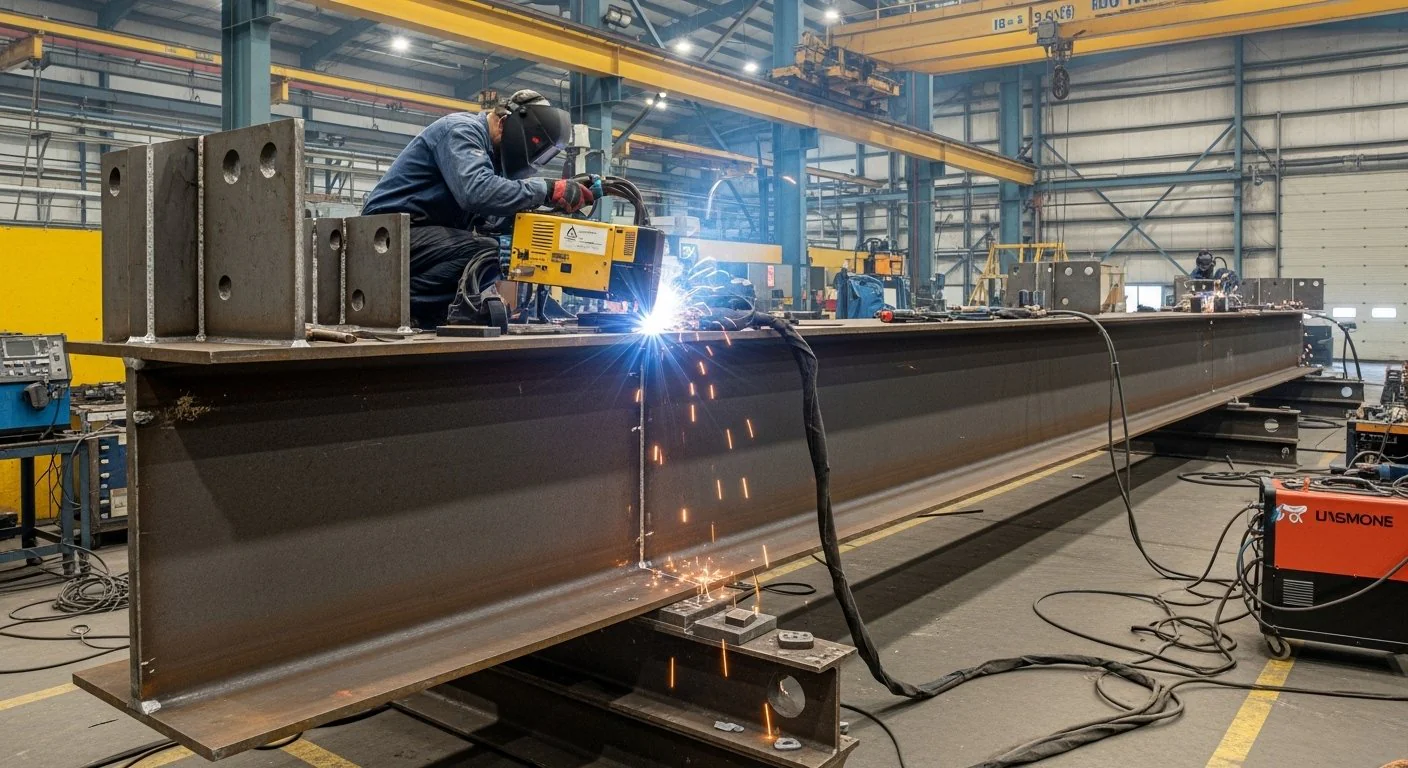
Span and load cases set overall depth and flange area. Shear in the web, bending in the flanges, and deflection limits all appear on the design drawings. Web buckling is controlled by stiffener spacing and thickness. Connection design — bolted splices, bearing seats, and diaphragm attachments — must match the erection plan so site joints do not become field-welded improvisations.
Camber, where specified, is built into fit-up and checked before welding. Once the flange-to-web welds are complete, correcting camber on thick plate is rarely practical. That is why shop drawing review and first-article fit-up matter more on plate girders than on light rolled framing.
Transport length and lift weight also shape the fabrication approach. A girder that is continuous on the design drawing may need shop or site splices to leave the workshop and reach the bearings. Splice locations should be agreed with the erection plan before cutting starts, because adding a splice after flanges are welded means cutting into completed work and reopening NDT hold points.
Fatigue detailing matters on crane runway segments and on spans with frequent moving loads. Weld profiles, stiffener terminations, and attachment details must follow the approved drawings rather than shop convenience, because a small change in weld termination can create a stress concentration the design never intended.
Shop capabilities
| Process | Application |
|---|---|
| CNC plasma cutting | Web and flange plates to net size |
| Submerged arc welding (SAW) | Longitudinal and flange-to-web fillet/butt welds |
| FCAW / SMAW | Stiffeners, diaphragms, splice plates |
| Plate thickness | 16 mm to 100 mm carbon steel (see heavy fabrication page) |
| NDT | UT on full-penetration welds; MPI on critical details |
| Pre-heat | Controlled preheat on thick plate per WPS |
Fabrication process
- Engineering review — approved shop drawings, WPS, and ITP hold points confirmed before cutting.
- Plate cutting and edge preparation — CNC plasma cutting of webs and flanges to net size, with edge prep for the weld detail shown.
- Fit-up — web, flanges, and stiffeners assembled; camber and square checked.
- Welding — SAW for long flange-to-web runs; FCAW/SMAW for stiffeners and splice plates, with controlled preheat on thick plate per WPS.
- Straightening — distortion control so flange alignment and camber stay within drawing limits.
- Inspection and NDT — dimensional checks, visual weld inspection, UT on full-penetration welds, MPI on critical details.
- Surface preparation and painting — blast, primer, and finish system per project specification.
- Dispatch — piece-marked girders in erection sequence with splice hardware where required.
Quality control
Inspection follows the project ITP. Typical activities include dimensional checks of depth, length, camber, and flange alignment; fit-up verification before welding; visual weld inspection; UT on full-penetration welds; and MPI on critical details. Customer inspection and third-party inspection are accommodated when specified. Material and weld traceability are maintained through to the quality dossier.
Because thick-plate welding is sensitive to procedure control, WPS parameters — preheat, interpass temperature, and consumables — are followed as qualified rather than adjusted on the floor for speed. Records stay with the girder mark so EPC and PMC reviewers can link each critical weld back to the procedure and NDT result.
Codes and sectors
Industrial and infrastructure girders are fabricated to IS 800:2007. Railway and highway ROB packages follow the project’s referenced code (IRS, IRC, or bridge design standard) as shown on the design drawings. We do not provide independent statutory structural design — we fabricate and erect to the approved design with full material and weld traceability.
For thick plate and large assemblies beyond standard building sections, see heavy fabrication.
Applications
- Industrial buildings, factories, and warehouses — long-span primary girders where rolled sections are insufficient
- Power plants and steel plants — heavy process and crane-related spans
- Cement plants — mill building and material-handling support girders
- ROB approaches and flyover packages — where the project drawings specify plate girders under IRS/IRC or the stated bridge design standard
- Pipe bridge longitudinals and industrial access spans
- Crane runway segments using plate girder methods
Surface protection
Finish follows the project specification. Typical workshop execution is blast cleaning with primer and an industrial paint system. Hot-dip galvanising is applied where specified and member sizes suit the process. Coating follows inspection hold points so shop repairs are limited to transport and erection damage.
Integration with other fabricated structures
Plate girder methods overlap with built-up beam fabrication for building frames and with crane runway girders for runway segments. Supporting columns may be built-up columns. Pipe bridge longitudinals sit within pipe bridge packages. Equipment platforms and supports often share the same industrial building frame — see equipment support structures. For overall capability see structural steel fabrication.
Technical specifications
| Item | Typical specification |
|---|---|
| Materials | IS 2062 plate (E250 / E350 as designed) |
| Plate thickness | 16 mm to 100 mm carbon steel (heavy fabrication for thicker/oversized) |
| Structural form | Welded I-girders and box sections; stiffeners, diaphragms, splice plates |
| Cutting | CNC plasma cutting of web and flange plates |
| Welding | SAW for flange-to-web; FCAW/SMAW for stiffeners and splices; WPS/PQR to IS 9595 |
| NDT | UT on full-penetration welds; MPI on critical details per ITP |
| Preheat | Controlled preheat on thick plate per WPS |
| Design / fabrication codes | IS 800:2007; IRS/IRC or project bridge standard where shown |
| Finish | Primer and industrial paint, or galvanising where specified |
Information required for quotation
- IFC drawings or enquiry GA showing span, depth, and camber
- Design loads and connection details
- Plate grades and thicknesses if already specified
- Whether splices, diaphragms, and rail seats are in scope
- Surface finish — paint system or galvanising
- Site location and erection constraints
Plate Girder Fabrication Cost in India (2026)
- Structural plate girder, IS 800, standard inspection, 600–1200mm depth: ₹85,000–₹1,05,000 per MT ex-workshop, fabricated and primed.
- ROB bridge plate girder, IRS B1, UT and MPI, 1200–2500mm depth: ₹95,000–₹1,20,000 per MT ex-workshop, painted to IRS specification.
- Crane runway beam plate girder, IS 807, UT and MPI: ₹1,05,000–₹1,45,000 per MT ex-workshop depending on crane capacity and web plate thickness.
- Box girder, IS 800, standard inspection: ₹1,05,000–₹1,30,000 per MT ex-workshop.
- Transfer girder, heavy section, full NDT: ₹1,20,000–₹1,60,000 per MT ex-workshop.
Final pricing depends on drawing review, span, inspection category and painting specification. Share the structural drawing, span, material grade and inspection requirements for a quotation within 24 hours.
Related fabricated scope
Plate girder fabrication FAQs
What plate thickness can you fabricate for plate girders?
Shop capability covers carbon steel plate from 16 mm to 100 mm. Thicker or oversized assemblies are coordinated under heavy fabrication scope as shown on the drawings and ITP.
When is SAW used versus FCAW or SMAW on plate girders?
Submerged arc welding (SAW) is used for long flange-to-web and longitudinal welds. FCAW/SMAW are used for stiffeners, diaphragms, and splice plates, per the approved WPS.
What NDT is typically applied on plate girder welds?
Full-penetration welds are checked by ultrasonic testing (UT). Magnetic particle inspection (MPI) is applied on critical details as required by the project ITP.
Which codes apply to ROB and industrial plate girders?
Industrial girders are fabricated to IS 800:2007. Railway and highway ROB packages follow the project’s referenced code (IRS, IRC, or the bridge design standard) shown on the design drawings. We fabricate and erect to the approved design; we do not provide independent statutory structural design.
What do you need for a plate girder RFQ?
Send IFC drawings or an enquiry GA. We respond within 24 hours and issue a quotation within 48–72 hours when drawings are available.
Where are plate girders typically used?
Common applications include road-over-bridge approaches, industrial access spans, crane runway segments, and pipe bridge longitudinals — wherever welded plate I-girders or box sections are specified instead of rolled beams.
Why use a plate girder instead of a rolled beam?
Plate girders are used when span, depth, flange thickness, or load demand exceeds what standard rolled sections can provide. The web and flanges are sized independently so material goes where the design needs it.
What is controlled preheat used for?
Controlled preheat on thick plate is applied per the WPS before welding, to reduce the risk of hydrogen cracking and to meet the procedure qualification for the plate thickness being joined.
Do you fabricate variable-depth plate girders?
Yes, where the approved shop drawings show variable or haunched depth. Camber and depth transitions are set during fit-up and checked before welding locks the geometry.
How are plate girders related to crane girders and built-up beams?
Crane runway segments often use the same plate girder methods. Built-up beams for building frames follow similar web-and-flange assembly at lighter plate thicknesses. See built-up beam fabrication and crane girder structures for those scopes.
Plate girder fabrication India — enquiry
Plate and built-up fabrication at Jeedimetla, Hyderabad — IS 2062 plate and sections, IS 800:2007, WPS/PQR to IS 9595, in-house UT/MPI. Manufacturer credentials · structural steel workshop scope · heavy plate fabrication
RFQ: Send IFC drawings or enquiry GA to Contact Sun Corporation. Response within 24 hours; quotation within 48–72 hours when drawings are available.