
Built-Up Beam Fabrication India
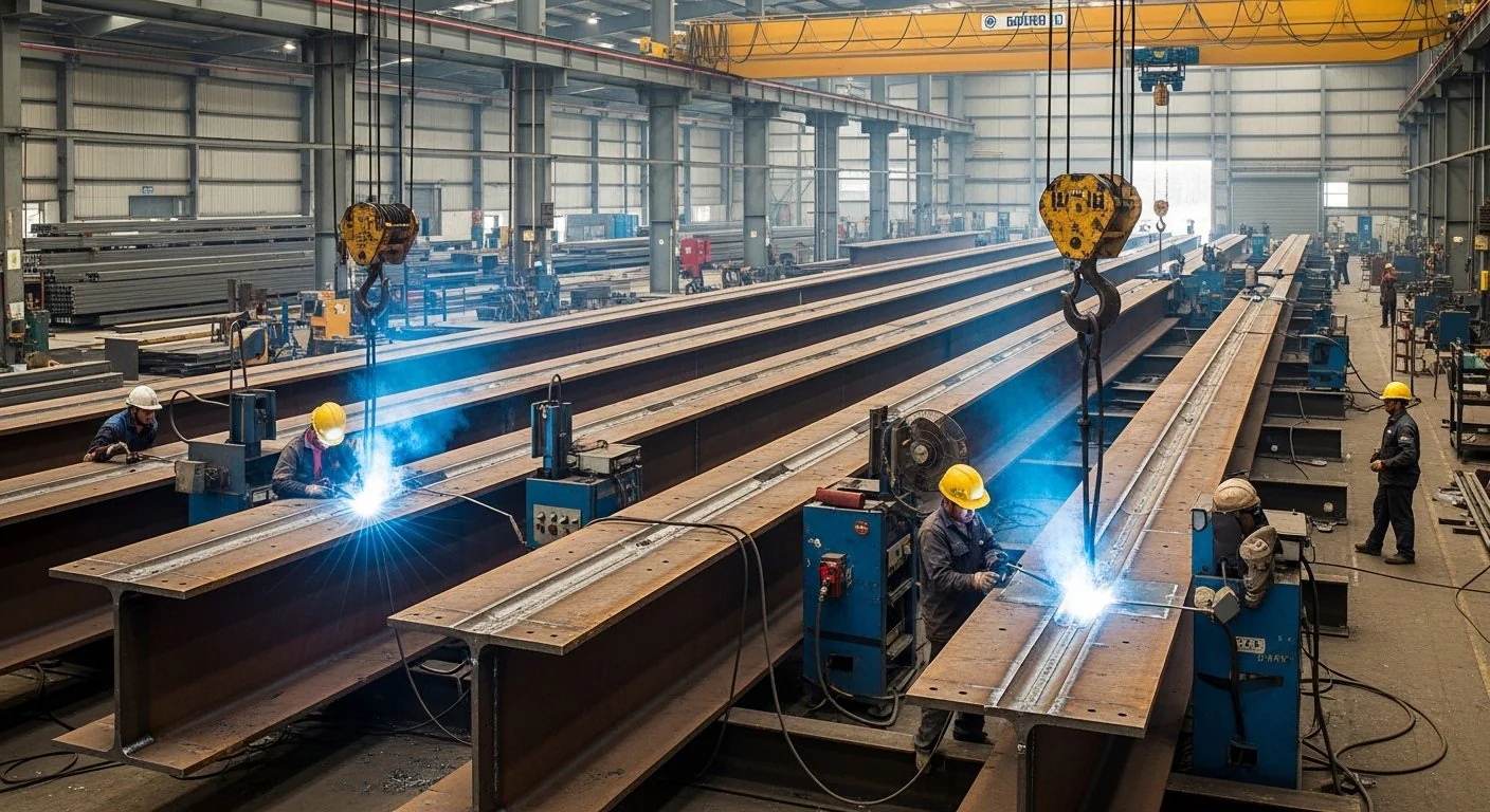
Built-up beams are fabricated I-sections assembled from plate — top flange, bottom flange, and web — when the required depth, weight, or span exceeds standard rolled UB/UC availability, or when the designer needs a non-standard section for a specific load case. Sun Corporation fabricates built-up beams for pipe rack longitudinals, platform girders, crane runway segments, and industrial building primary frames.
A rolled beam is efficient when the catalogue section matches the design. When it does not — when the web needs to be deeper, the flange thicker, or the proportion unusual — a built-up beam lets the engineer size each plate separately. That is why EPC packages for pipe racks, process platforms, and heavy industrial frames so often call for welded plate I-sections instead of relying only on mill sections.
Loads on GA drawings are developed per IS 875 by the structural engineer. We fabricate to approved member sizes and shop drawings — we do not redesign. For design theory on plate assemblies, see our Plate Girder Design Guide.
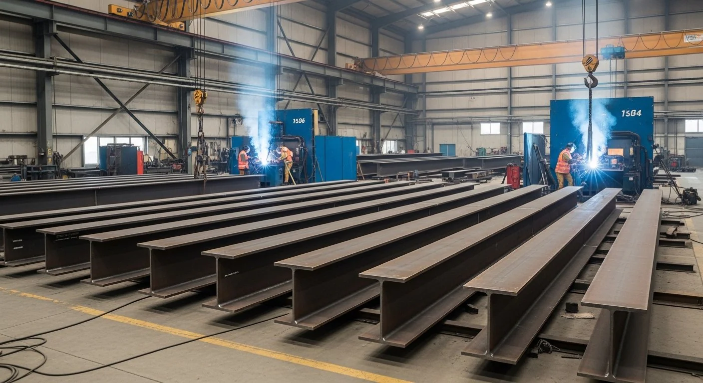
When EPC specs call for built-up sections
- Pipe rack beams spanning between bents with heavy piping clusters
- Transfer beams supporting multiple equipment lines
- Long-span platform girders in process areas
- Crane runway beams where rolled sections cannot meet IS 807 span/loading
- Plate girders for access bridges and conveyor supports
Types of built-up beams
- Welded built-up beams — standard shop-welded I-sections from web and flange plates for racks, platforms, and industrial frames.
- Heavy-duty built-up beams — thicker flanges and webs for crane runway segments, heavy transfer beams, and long-span industrial girders.
- Variable-depth / haunched beams — depth varied along the span as shown on the drawings for support moments or clearance constraints.
- Long-span beams — primary girders where rolled catalogues cannot meet depth or deflection limits.
- Custom fabricated beams — non-standard flange widths, web depths, or attachment plates detailed for a specific load case.
Structural components
- Web plate — vertical plate carrying shear between flanges.
- Top and bottom flanges — plate flanges sized for bending.
- Stiffeners — bearing and intermediate stiffeners where the drawing requires buckling or bearing control.
- End plates and connection plates — shop and site connection details for splices and seating.
- Attachments — cleats, rail seats, and secondary connection plates per the GA.
Materials
Material is IS 2062 E250 BR or E350 BR plate as project-specified, with mill test certificates indexed to piece marks on every dispatch. E250 is typical for pipe rack longitudinals, secondary platform girders, and light industrial frames. E350 is the usual choice for crane runway segments, heavy transfer beams, and long-span industrial girders. Universal sections may appear in bracing or secondary members where the design specifies them. See our IS 2062 Steel Grades Guide for grade comparison.
| Grade | Yield (MPa) | Typical Built-Up Use | Procurement Note |
|---|---|---|---|
| IS 2062 E250 | 250 | Pipe rack longitudinals, secondary platform girders, light industrial frames | Lower material cost; may need deeper section |
| IS 2062 E350 | 350 | Crane runway segments, heavy transfer beams, long-span industrial girders | Standard for heavy IS 2062 beam fabrication packages |
Design considerations
Span, bending, and shear set overall depth and plate sizes. Deflection limits keep platforms and rack tiers serviceable under live and piping loads. Lateral stability — through bracing, flange proportions, and connection restraint — must match the frame design. Connection details for bolted splices and beam seats should be fixed before shop drawings are released so fabrication and erection stay aligned.
Where built-up runway beams are in scope, crane loads follow IS 807 on the design drawings. We fabricate the member sizes shown; we do not reinterpret crane vendor data.
Splice locations are another early decision. A beam that is continuous on the GA may need shop or site splices to leave the workshop and reach the bearings. Agreeing those splices with the erection plan before cutting starts avoids adding joints into finished flange-to-web welds later. Piece marks linked to the GA keep every beam traceable from plate heat number through to site position.
Fit-up quality decides weld quality. Jig-aligned assembly keeps the web centred between flanges and holds camber while SAW runs the long seams. Distortion control after welding — and a final check of camber and sweep against IS 800 Annex F — is what prevents a beam that looks correct in the shop from failing dimensional acceptance at dispatch.
Fabrication process
- Drawing release — shop drawings approved; piece marks and splice locations locked
- Plate procurement — IS 2062 plate verified against MTC before cutting
- CNC cutting — web and flange plates cut to length and bevel as required
- Fit-up & welding — jig-aligned assembly; SAW on long flange-web seams; FCAW where the WPS requires
- Stiffeners & attachments — bearing, intermediate and connection plates per drawing
- NDT & dimensional check — camber, sweep and weld inspection per ITP against IS 800 Annex F
- Blast, paint & dispatch — marked modules sequenced to site erection programme
Full workshop capability is outlined on our structural steel fabrication page. Plant layout is on our Hyderabad steel fabrication workshop.
Quality controls
Each built-up beam is fabricated to approved shop drawings with piece marks linked to the GA. Flange-to-web welds are executed under qualified WPS with NDT as listed in the ITP. Camber and sweep are checked against fabrication tolerances in IS 800 Annex F before dispatch. Material is IS 2062 with MTCs in the project dossier.
QC aligns with EPC inspection test plans: material heat-number traceability, WPS ID on every coded weld, UT or MPI on flange-web joints where specified, and dimensional reports against IS 800 fabrication tolerances before dispatch release. Non-conforming beams are held until rework or documented concession — supporting PMC and licensor review without programme delay. Customer inspection is accommodated when specified.
Companion scope: built-up column fabrication and plate girder fabrication.
Applications
- Warehouses and logistics — long-span roof girders and mezzanine primary beams
- Industrial plants, factories, and heavy engineering — process area platform girders, transfer beams, and machine-base tie beams
- Steel plants, power plants, and cement plants — heavy process and material-handling frames
- Refineries and petrochemical — multi-tier pipe rack beams sized for piping clusters and wind per IS 875
- Manufacturing facilities — crane runway segments and access bridge girders
- Data centers — heavy roof and equipment support girders over long bay widths
Built-up members are often released in the same purchase order as fabricated steel columns and rack bents for coordinated erection sequencing on site.
Surface protection
Typical surface treatment is shot blast Sa 2.5 with primer and paint, or hot-dip galvanising (HDG) per the project specification. Where the coating schedule calls for an industrial paint system after primer, we follow the approved DFT and colour references on the project data sheet. Coating follows inspection hold points so shop damage is limited to transport and erection touch-up.
Integration with other fabricated structures
Built-up beams sit alongside fabricated plate girders for longer spans, built-up columns in the same frames, and crane girder structures where runway segments use the same plate methods. They appear throughout pipe rack packages, equipment support structures, and industrial building primary frames. For overall capability see structural steel workshop scope and heavy steel fabrication.
Technical specifications
| Parameter | Typical Range / Standard |
|---|---|
| Material grade | IS 2062 E250 BR / E350 BR (project specified) |
| Section type | Welded I-section; parallel or haunched flanges per drawing |
| Web thickness | 6 mm – 16 mm (heavier on engineering review) |
| Flange width | 150 mm – 600 mm typical industrial range |
| Overall depth | 300 mm – 2,000 mm+ per structural design |
| Design & fabrication code | IS 800:2007; loads per IS 875 on GA drawings |
| Welding | SAW / FCAW on flange-web joints; IS 816 / IS 9595 WPS |
| NDT | UT / MPI per project ITP on coded welds |
| Surface treatment | Shot blast Sa 2.5; primer / paint or HDG per spec |
| Documentation | MTCs, weld maps, NDT reports, dimensional records |
| Standard | Role on Built-Up Beam Packages |
|---|---|
| IS 2062 | Plate and section material grades; MTC requirements |
| IS 800:2007 | Design basis on GA; fabrication tolerances and acceptance |
| IS 875 | Dead, live and wind loads used by consultant in member sizing |
| IS 816 / IS 9595 | Welding procedure and welder qualification |
| IS 807 | Crane loads where built-up runway beams are in scope |
Code references: IS 800 Guide · IS 875 Structural Design Loads Guide
Information required for quotation
- IFC or enquiry GA showing span, depth, and connections
- Design loads and member sizes (or drawings from which they are taken)
- Coating specification — primer/paint or HDG
- Fabrication only versus fabrication-and-erection scope
- ITP / NDT requirements and documentation format for submittal registers
- Site location and dispatch sequence preferences
Related fabricated scope
Built-up beam fabrication FAQs
What built-up beam sizes can you fabricate?
We fabricate to approved shop drawings — typical industrial depths from 300 mm to 2,000 mm+ with web and flange plates per structural design. Send GA or enquiry drawings for capacity confirmation.
Do you supply material test certificates?
Yes. IS 2062 plate and sections are supplied with mill test certificates indexed to heat numbers and piece marks in the EPC dispatch dossier.
What is the difference between built-up beam and plate girder fabrication?
Both use welded plates; plate girders often imply longer spans with formal stiffener design per IS 800. We fabricate both — see plate girder fabrication and the Plate Girder Design Guide.
What should an EPC RFQ include for built-up beams?
IFC or enquiry GA, coating specification, fabrication vs fabrication-and-erection scope, ITP/NDT requirements and required documentation format for submittal registers.
What is your response time for built-up beam enquiries?
Technical acknowledgement within 24 hours; quotation within 48–72 hours when drawings and scope boundaries are available.
When do EPC specs call for built-up beams instead of rolled sections?
When depth, weight, or span exceeds standard rolled UB/UC availability, or when the designer needs a non-standard section — for example pipe rack longitudinals with heavy piping clusters, transfer beams, long-span platform girders, or crane runway beams that cannot meet IS 807 with rolled sections.
Which steel grades are used?
IS 2062 E250 BR or E350 BR as project-specified. E250 is common for pipe rack longitudinals and secondary platform girders; E350 for crane runway segments, heavy transfer beams, and long-span industrial girders.
How are camber and sweep checked?
Camber and sweep are checked against fabrication tolerances in IS 800 Annex F before dispatch. Flange-to-web welds are executed under qualified WPS with NDT as listed in the ITP.
What surface treatment is applied?
Typical finish is shot blast Sa 2.5 with primer and paint, or hot-dip galvanising (HDG) per the project specification.
Do you redesign member sizes?
No. Loads on GA drawings are developed per IS 875 by the structural engineer. We fabricate to approved member sizes and shop drawings — we do not redesign.
Built-up beam fabrication India — enquiry
Plate and built-up fabrication at Jeedimetla, Hyderabad — IS 2062 plate and sections, IS 800:2007, WPS/PQR to IS 9595, in-house UT/MPI. Manufacturer credentials · IS 800 structural steel fabrication · heavy fabrication
RFQ: Send IFC drawings or enquiry GA to Contact Sun Corporation. Response within 24 hours; quotation within 48–72 hours when drawings are available.