
Utility Pipe Racks India
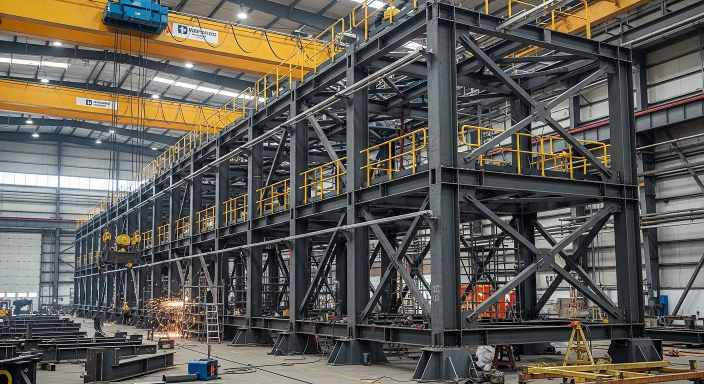
Utility pipe racks carry the service piping that keeps a process plant running — steam, condensate, cooling water, compressed air, fuel gas, and firewater loops. They are often specified separately from process pipe racks in EPC BOQs. Sun Corporation fabricates utility racks as IS 800:2007 compliant steel structures from IS 2062 material, with the same WPS/PQR and inspection trail as main process racks.
Utility steel is sometimes treated as lower priority than main process racks, which is a mistake in scheduling terms. Steam, cooling water, instrument air, and firewater are needed for commissioning, so utility corridors are often required earlier than the process lines they serve. Late utility steel delays commissioning even when the main rack is complete.
The technical demands are also different rather than lighter. Utility routes weave between existing structures, cross roads at awkward angles, and tie into live headers. Retrofit connections to operating plant need survey data, careful sequencing, and often a shutdown window — constraints that shape both the design and the way the steel is fabricated and delivered.
Scope differences from process racks
Utility racks frequently run at lower elevations, tie into existing corridors, or span between equipment areas and the main pipe rack battery limits. That means more short spans, more retrofit connections, and tighter coordination with live-plant interfaces. We fabricate in modular shop assemblies where the erection sequence allows — reducing hot-work time on site.
| Typical utility services | Fabrication notes |
|---|---|
| Steam and condensate | Thermal movement guides; elevated support spacing per stress analysis |
| Cooling water | Heavier pipe clusters; wider bent spacing on long runs |
| Instrument and cable tray supports | Secondary steel attached to rack columns or cantilever brackets |
| Firewater | Seismic bracing where specified; galvanised or painted finish per spec |
Reducing hot work matters most on brownfield sites. Every field weld near live piping needs a permit, gas testing, and often a fire watch, all of which consume site hours. Shifting welded connections into the workshop and leaving bolted joints for site turns a permit-controlled activity into a straightforward assembly task.
Structural components
- Columns and bents — the transverse frames carrying tier loads to foundations.
- Longitudinal beams — members spanning between bents to support pipe runs at each tier.
- Transverse tier beams — members carrying individual lines and pipe shoes across the rack width.
- Cantilever brackets — outriggers for cable trays, instrument lines, and small-bore services.
- Bracing — vertical and plan bracing for wind and, where specified, seismic actions.
- Base plates and anchor templates — shop-drilled to the approved pattern and issued to civil before pour.
- Access steel — walkways, ladders, and platforms where maintenance access is in scope.
Materials
Fabrication uses IS 2062 sections and plate to the grades shown on the drawings. Finish follows the project specification for each service — galvanised or painted, with the coating system chosen for the exposure and temperature of the lines being supported. Grades and section sizes are not substituted without an approved concession, and mill certificates stay traceable to cutting lists.
Where a rack carries both hot and ambient services, the coating specification usually differs along the run. Those differences are captured on the shop route sheet so the right system is applied to the right marks rather than a single blanket finish.
Galvanising suits exposed utility corridors and firewater routes where long maintenance-free life is wanted, but it constrains fabrication: members must fit the bath, drainage and vent holes need detailing, and welding after galvanising requires local repair. Painted systems allow larger assemblies and easier site modification, which can matter on brownfield routes likely to be altered again. The choice is set by the project specification, and the fabrication approach follows from it.
Design considerations
Support spacing is set by the piping stress analysis, not by a standard rack grid. Steam and condensate lines expand, so guide and anchor positions have to be fabricated exactly where the piping design places them. Getting a guide position wrong transfers unintended load into the steel and can overstress the line.
Load cases combine pipe weight, contents, insulation, thermal effects, wind, and — where specified — seismic actions. Cooling water clusters are heavy and often govern member sizing on wide racks. Firewater loops may attract specific seismic bracing requirements because the system must survive an event and remain operable.
Tie-ins to existing corridors need dimensional survey rather than assumed geometry. Existing steel is rarely exactly where old drawings say it is, and a bolted connection detailed from a drawing alone often will not fit. Where possible, connection details allow adjustment within the erection tolerance rather than requiring field modification.
Elevation is another practical constraint. Utility routes commonly run lower than main process racks, which brings them into conflict with vehicle access, walkways, and equipment laydown areas. Clearance over roads and around maintenance access points has to be checked against the plant layout, not just the structural drawing, because a rack at a convenient structural height may block a crane route or a bundle pull.
Future expansion is worth deciding early. Utility corridors attract additional lines over a plant’s life more often than process racks do, and leaving spare tier capacity or provision for bracket attachment is far cheaper at fabrication stage than adding steel to a coated, loaded rack later.
Modular fabrication and site sequencing
Where the erection sequence allows, bents and one bay of tier steel are assembled as a module in the workshop and dispatched in erection order. The site then lifts a known-good assembly into place and completes bolted connections, rather than building the rack piece by piece at height.
Module size is limited by transport width and length, crane capacity at the location, and access along the route. Those limits are settled before shop drawings are finalised, because splitting a rack into modules after fabrication has started usually means adding splices that were never detailed. On congested brownfield sites, smaller modules that can be manoeuvred through existing structures often beat larger ones that need more space to place.
Fabrication process
- Engineering review — GA, piping support positions, and tie-in interfaces checked before shop drawings are released.
- Material procurement — IS 2062 sections and plate against cutting lists with mill certificates.
- Cutting and drilling — members, brackets, and connection plates processed to shop drawings.
- Modular assembly — bent plus tier modules assembled where the erection sequence allows.
- Welding — coded joints to qualified WPS/PQR (IS 9595).
- Inspection and NDT — per the project ITP, including UT/MPI where required.
- Surface preparation and finish — galvanising or paint system per specification.
- Marking and dispatch — piece marks included in the master dispatch list.
Quality and handover
Utility rack packages are often part of a larger EPC steel MTO. We match your ITP hold points, provide bolted connection records, and include utility rack piece marks in the master dispatch list. See manufacturer credentials for workshop capacity (500+ MT/month) and documentation samples.
Typical inspection activities include material verification, fit-up checks before welding, visual weld inspection, in-house Level II UT/MPI where the ITP requires it, dimensional checks of module geometry and bolt patterns, and coating inspection. Customer and third-party inspection are accommodated when specified.
Applications
- Refineries and chemical plants — steam, condensate, and utility corridors between units
- Power plants — auxiliary steam, cooling water, and firewater routes
- Cement and steel plants — compressed air, water, and fuel gas service lines
- Water and effluent treatment — process and service water headers
- Manufacturing facilities — plant air, chilled water, and utility distribution
- Brownfield expansions — retrofit utility routes tying into live corridors
Integration with other fabricated structures
Utility racks share battery limits with main process pipe racks, cross infrastructure on pipe bridges, and fall within the wider process plant structures package. Where service lines terminate at equipment, equipment support structures are usually fabricated alongside. For overall capability see structural steel fabrication.
Information required for quotation
- GA drawings or IFC structural drawings for the utility corridor
- Line list or pipe schedule with sizes, services, and operating temperatures
- Anchor, guide, and sliding support positions from the piping stress analysis
- Tie-in locations and any survey data for existing steel
- Whether cable tray and instrument supports are in scope
- Finish specification — galvanised or painted, by service
- Shutdown windows or live-plant access constraints
Related fabricated scope
Utility pipe rack FAQs
What services do utility pipe racks carry?
They carry the service piping that keeps a process plant running — steam, condensate, cooling water, compressed air, fuel gas, and firewater loops. These are often specified separately from process pipe racks in EPC BOQs.
How do utility racks differ from process pipe racks?
Utility racks frequently run at lower elevations, tie into existing corridors, or span between equipment areas and the main pipe rack battery limits. That means more short spans, more retrofit connections, and tighter coordination with live-plant interfaces.
How is steam and condensate piping supported?
Thermal movement guides are provided and support spacing at elevated temperature follows the piping stress analysis. Anchor, guide, and sliding support positions come from the piping design and are built into the fabricated steel.
What changes for cooling water lines?
Cooling water means heavier pipe clusters, so bent spacing is widened on long runs only where the design allows and member sizes reflect the increased load.
Can cable trays and instrument lines share the rack?
Yes. Secondary steel for instrument and cable tray supports is attached to rack columns or provided as cantilever brackets, per the drawings.
How are firewater lines handled?
Seismic bracing is provided where specified, and the finish is galvanised or painted per the project specification for the exposure and service.
Do you fabricate in modules?
Yes. We fabricate in modular shop assemblies where the erection sequence allows, which reduces hot-work time on site — particularly valuable on live-plant tie-ins.
Which standards apply?
Utility racks are fabricated as IS 800:2007 compliant steel structures from IS 2062 material, with the same WPS/PQR and inspection trail as main process racks.
How is documentation handled within a larger EPC package?
Utility rack packages are often part of a larger EPC steel MTO. We match your ITP hold points, provide bolted connection records, and include utility rack piece marks in the master dispatch list.
What is needed for a quotation?
Send GA drawings, piping layouts, or a scope note. Preliminary response is within 24 hours on working days; a detailed quotation follows within 48–72 hours when IFC or enquiry drawings are available.
Utility Pipe Racks India — Enquiry
Fabrication is carried out at our Jeedimetla, Hyderabad workshop under IS 800:2007 with IS 2062 material, qualified WPS/PQR to IS 9595, and in-house Level II UT/MPI. For EPC prequalification packs, see our workshop credentials. For full fabrication scope, see structural steel workshop scope and heavy steel fabrication.
Send GA drawings, piping layouts, or a scope note for RFQ: Contact Sun Corporation — preliminary response within 24 hours on working days; detailed quotation within 48–72 hours when IFC or enquiry drawings are available.